In our previous article of this series, Control Systems, control loops, and control loop elements were briefly introduced, and only surface regarding control loop elements was scratched. In this article, an introduction of some important elements of control systems that measure physical quantities of a process i.e., sensors, transducers, and transmitters will be explored. Together these are used not only to sense but also to convert and transmit a process parameter into some appropriate form of signal suitable for controllers to process them.

Table of Contents
What is a Sensor?
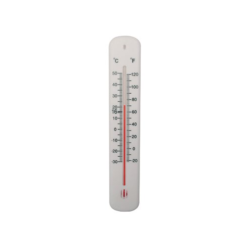
A sensor is a device that can sense or detect a physical quantity and can generate a measurable output which is a function of the amplitude of physical quantity. These measurable outputs can be in the forms of visual indication like in a glass thermometer, the temperature is indicated by a visual reading or some other form like thermocouples produce a voltage on sensing temperature.
Types of Sensors
Sensors are classified on the basis of physical quantities to be measured. The sensor used for measuring level, pressure, temperature, and flow are called level, pressure, temperature, and flow sensors respectively.


Working of Sensors (An Example)
The working of sensors, irrespective of the type of sensor (level, pressure, temperature, flow, etc.) is based on the change/movement in some parameters dictated by the change in the measuring parameter. This change or movement is detected or read by using some scale. Values on the scale is properly adjusted for measurement purpose such that reading on a scale truly represents the exact value of the parameter.
For example, in float level sensors, change in level produces movement in rope or wire attached to some counterweight which is measured against the scale as shown in the figure below:

As the water level in the tank rises; the float moves upwards causing a counterweight to move upward or downward depending on the pulley scheme used. Movement of counterweight is properly scaled or calibrated against the water level in the tank. In this way, the level of water is measured visually. The same is true in case of water level reduces in the tank causing the counterweight to move in the direction dictated by the pulley scheme and scale is read to find the level of water in the tank.
What is a Transducer?
A transducer is a device that converts one form of energy into another form so it can be used for further processing. For example, resistance thermometers convert temperature into electrical resistance which is further converted into voltage. So, unlike ordinary glass thermometers, which acts as only a sensor, resistance thermometers act as transducers. The output of transducers, needless to say, is some function of the amplitude of measuring parameter.
Output generated by sensors cannot be used for electronics and electrical devices unless or until converted into another form. Output produced by level sensor discussed in the example of a sensor, cannot be fed to the controller or some other equipment. Therefore, transducers serve as the intermediate connection between sensors and control devices.

Types of Transducers
Transducers are classified into the following different types:
Transducers are named as level, pressure transducers, etc., just like sensors, on the basis of a physical parameters to be measured.
Transducers are also divided into current transducers or voltage transducers based on the output signal generated by transducers.


Working of Transducers (An Example)
The working principle of transducers is to convert a change in some electrical property (resistance, capacitance, etc.) into current or voltage in response to a change in the physical parameters. As the amplitude of physical quantity changes, electrical property changes, so does the voltage and current generated, proportional to amplitude.
For example, in the following figure, a float level transducer assembly is shown. The sensor part is almost the same as the previously discussed example but to make a transducer, one additional variable resistance or potentiometer is attached with the sensor. As the float rises with the water level, the pointer connected to the weight also moves.

The pointer in this case is the variable leg of a potentiometer. This potentiometer is a part of some electrical circuit as shown. As resistance changes because of movement of weight which is caused by change in water level in the tank, the voltage changes. So, a change in water level is finally depicted in the form of voltage change. Now, this form of energy (voltage) can be used by controller to control the process.
What is a Transmitter?
Transmitters are devices used for processing (amplification, formatting) of signals for its transmission to controllers. As Transducers and controllers can be a great distance apart in a plant, therefore, signals produced by transducers are needed to be transmitted with minimal or almost zero loss, to controllers for precise monitoring and control purposes.

Types of Transmitters
Transmitters are divided into following different types:
Transmitters are named as level, pressure transmitters, etc., just like sensors and transducers, on the basis of measuring quantity or input to the transmitters.
Transducers are divided into current transducers or voltage transducers based on output signal generated by transducers.
Transmitters are also grouped based on signal types. Transmitted signals can be analog or digital. Analog Signals are transmitted into different forms of voltages and currents. Most commonly types of transmitted signals to controllers are 0~20 mA, 4~20 mA, 0~5V and 0~10V DC signals. While in digital signals, different communication protocols like HART bus, Foundation Field bus and Mod bus are used. Now a days, digital signals are preferred over analog but both have advantages and disadvantages associated with them.
Working of Transmitters (An Example)
The basic working of transmitters is almost the same as transducers. The signal is amplified and formatted such that amplitude changes from lowest value to highest value as physical parameter changes from lowest to highest units. Transmitters are calibrated so that lowest signal value is the representation of lowest process parameter value.
For example, the following figure shows a flow transmitter for measuring flow in the range of 0~100 m3/h. Flow is converted into current and transmitted to Controller (DCS, PLC) via cables.
The whole span of flow which is to be monitored is divided between 4 mA to 20 mA such that the lowest value of flow (0 m3/h) is represented by 4mA and the highest value of flow (100 m3/h) is represented by 20mA while 0 mA is usually the representation of the open circuit. When the flow is at the lowest level to be measured i.e. 0 m3/h, the transmitter produces signal of 4mA. As the water flow rises in a pipe, current output produced by the transmitter increases too and becomes 20mA when flow reaches 100 m3/h. Present value, as shown in the figure, is 12 mA indicating the flow of 50m3/h. Proper calibration enables controller to find liquid flow on receiving the current output from the transmitter and use it to generate control signals.
Summary
Sensors, Transducers and Transmitters are very important components of a control system. Sensors detect the change in physical parameters whereas transducers convert it into some electrical signal suitable for processing. Transmitters convert it into a form suitable for transmission over long distances. These are properly calibrated such that final output signal or output of transmitter fed to the controllers is the true representation of amplitude of measured variable.
I hope you’ve liked this article series on the introduction of Control Systems. You may also like our detailed article on the working and construction of a power system and Load flow analysis in ETAP software.
To keep updated with the latest articles, you can subscribe to the website through the bell icon on the lower-left corner to receive further updates. Visit and subscribe to our YouTube channel for video tutorials and stay updated by following our Facebook page.


Jack says
Hi there! This is some nice work, I have checked all the necessary topics that I need and was really amazed that I found all related to them very quickly. I have also found this amazing website that teaches for free and also provides free solutions. make sure you check them as well.