Transformer Inrush Current: Why Relays Nuisance-Trip and How to Set Around It

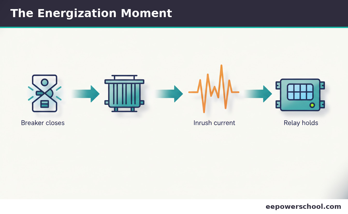
Close a breaker onto an unloaded transformer and, for a few cycles, it can draw many times its rated current, a surge that to a relay looks almost exactly like an internal fault. That surge is transformer inrush current, and it is the reason differential and instantaneous elements nuisance-trip on energization if they are not set with it in mind.
This article explains what causes inrush, why it mimics a fault, and the one feature that reliably tells them apart: harmonic content. We then walk through setting the instantaneous (50) and differential (87) elements to ride through inrush, the modern low-second-harmonic trap, and a worked settings example.
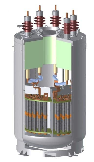
What Transformer Inrush Current Is
A transformer’s core is designed to operate just below magnetic saturation. When it is energized, the flux required depends on the exact point on the voltage wave at the instant of closing and on any residual flux left in the core from the last de-energization. In the worst case, the required flux adds to the residual and drives the core deep into saturation.
A saturated core has very low inductance, so it draws a large magnetizing current to sustain the flux. That large, distorted magnetizing current is the transformer inrush current. It is not a fault, just the core demanding magnetizing current it briefly cannot get without saturating, but its magnitude is alarming.
Why Inrush Looks Like a Fault
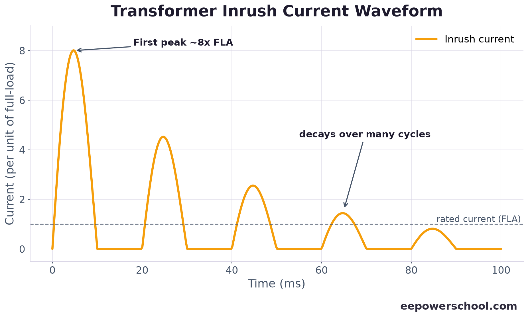
Inrush is dangerous to protection precisely because, on the face of it, it resembles a fault. The first peak can reach roughly 6 to 10 times the transformer’s rated full-load current, comparable to a real fault, and because it flows into the transformer but not out, a differential relay sees it as differential current, exactly the signature of an internal fault.
It is also offset and unidirectional at first, appearing as a series of decaying current pulses rather than a symmetric sinusoid. The surge then decays over many cycles, sometimes a second or more on large units. Left to itself, an instantaneous or differential element would simply trip, which is the nuisance trip we are trying to prevent. The waveform below shows the characteristic decaying pulses.
The Key Difference: Harmonic Content
The feature that saves the day is harmonics. Because the saturated-core magnetizing current is heavily distorted, transformer inrush current is rich in second harmonic (twice the fundamental, 100 or 120 Hz). An internal fault, by contrast, produces differential current that is largely fundamental, with very little second harmonic.
That contrast is the basis of secure transformer protection: a high proportion of second harmonic almost certainly means inrush, not a fault. Relays therefore measure the second-harmonic content of the differential current and use it to decide whether to allow a trip, the single most important idea in distinguishing inrush from a genuine fault.
Second-Harmonic Restraint and Blocking
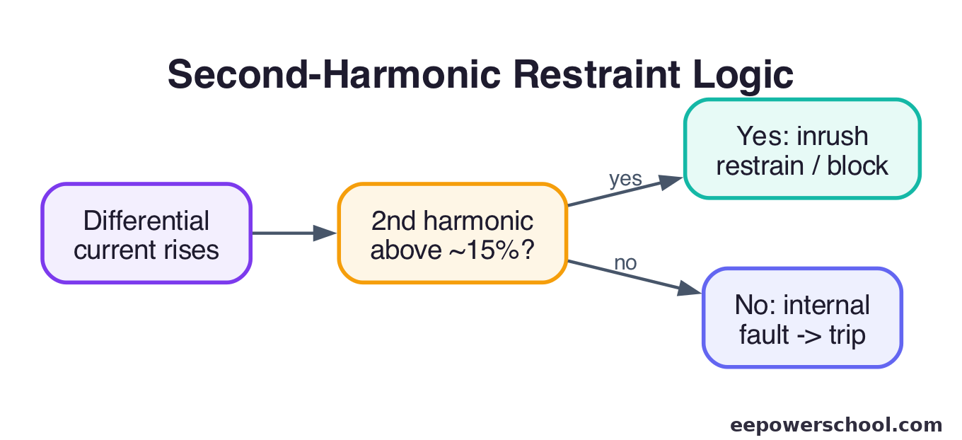
Differential relays exploit the harmonic signature in one of two ways. With harmonic restraint, the measured second harmonic is added to the relay’s restraint quantity, so a differential current rich in second harmonic is much harder to trip on. With harmonic blocking, the trip is outright inhibited whenever the second-harmonic ratio exceeds a set threshold, commonly around 15 to 20% of the fundamental.
Both keep the 87 element secure during energization while remaining fast for real internal faults, which lack the harmonic. The relay logic, illustrated below, is essentially: is the second harmonic high? If yes, this is inrush, hold; if no, it is a fault, trip.
Setting the Instantaneous Overcurrent (50)
The unrestrained instantaneous overcurrent element is the most likely to misoperate on inrush, because it reacts to magnitude alone with no harmonic discrimination. There are two classic approaches.
The first is to set the high-set instantaneous element above the maximum inrush peak, typically above the 8 to 10 times rated current that energization can produce, so only a severe fault, which pushes current even higher, can pick it up. The second is to apply a short time delay or harmonic supervision so the element ignores the brief inrush transient. The goal is the same: keep the 50 element from seeing inrush as a reason to trip while preserving fast clearing for real high-current faults.
Setting Differential (87) with Harmonic Restraint
For the differential element, security against inrush comes from the harmonic settings rather than raw pickup. Enable second-harmonic restraint or blocking and set the threshold, often near 15%, low enough to catch genuine inrush but high enough not to block on a real fault that happens to carry some harmonic from CT saturation.
The percentage-differential slope and minimum pickup are then set for through-fault stability and CT error in the usual way. The harmonic feature is the layer that specifically addresses energization. IEEE Std C37.91 is the standard reference for these choices, and the worked example later puts representative numbers on them.
The Low-Second-Harmonic Trap
A modern complication deserves a warning. Today’s low-loss amorphous and high-grade core steels can produce inrush with lower second-harmonic content than older designs, sometimes dipping below a 15% blocking threshold. If that happens, the relay may not recognise inrush and can trip on energization anyway.
Mitigations include lowering the second-harmonic threshold, using cross-blocking (blocking all three phases if any one phase detects inrush), or relays with waveform-based or adaptive inrush detection that does not rely solely on a fixed harmonic ratio. The lesson is to confirm the inrush harmonic content of the actual transformer rather than assuming the textbook value.
Worked Settings Example
Take a 20 MVA, 33/11 kV transformer. Its full-load current on the 11 kV side is roughly 1050 A. Representative settings to ride through transformer inrush current:
| Element | Consideration | Representative setting |
|---|---|---|
| Differential pickup (87) | Above CT/tap mismatch error | ~0.3 x rated differential current |
| 2nd-harmonic restraint/block | Inrush ~15-30% 2nd harmonic; faults <5% | 15% threshold |
| Differential slope | Through-fault & CT saturation stability | 25-40% |
| High-set instantaneous (50) | Above max inrush peak (~8-10x FLA) | > ~10,500 A (10x FLA) |
With these, energization inrush is restrained by the harmonic logic and stays below the high-set instantaneous, while a real internal fault, low in second harmonic and often very high in magnitude, trips quickly. For coordination fundamentals, see our guide on protection coordination.
Frequently Asked Questions
What causes transformer inrush current?
Energizing a transformer at an unfavourable point on the voltage wave, combined with residual flux in the core, drives the core into deep saturation. A saturated core has very low inductance and draws a large, distorted magnetizing current, the inrush, until the flux settles over the next several cycles.
How large is transformer inrush current?
The first peak typically reaches about 6 to 10 times the transformer's rated full-load current, comparable to a fault. It is offset and unidirectional at first, appearing as decaying current pulses, and fades over many cycles, sometimes a second or more on large units.
How do relays tell inrush apart from a fault?
By harmonic content. Inrush current is rich in second harmonic because the saturated-core magnetizing current is heavily distorted, while internal-fault differential current is largely fundamental. A high second-harmonic ratio, often above 15%, indicates inrush, so the relay restrains or blocks the trip.
What is second-harmonic restraint?
It is a differential-relay feature that uses the second-harmonic content of the differential current to stay secure during energization. Restraint adds the harmonic to the relay's restraint quantity; blocking inhibits the trip when the second-harmonic ratio exceeds a threshold, commonly around 15 to 20%.
Why might second-harmonic blocking fail on modern transformers?
Modern low-loss core steels can produce inrush with lower second-harmonic content, sometimes below a 15% threshold, so the relay may not recognise it as inrush. Fixes include lowering the threshold, cross-blocking all three phases, or using relays with adaptive, waveform-based inrush detection.
Related reading
- Protection coordination of a distribution network in ETAP
- Overcurrent relay: concepts and design in Simulink
- Faults in power systems: types, causes and arcing
- Electrical Engineering Formula Cheat Sheet (power systems quick reference)