RMS vs EMT Simulation: When Phasor Models Aren’t Enough
Ask an engineer to study a power system disturbance and the first real decision is which kind of simulation to run. The choice between RMS vs EMT models, phasor versus full electromagnetic transient, sets what you can see, how long it takes, and whether you can trust the answer at all. Pick wrong and you either waste weeks of compute or, worse, miss the instability you were hired to find.
That decision used to be easy: phasor (RMS) tools handled almost everything. The rise of inverter-based resources has changed the calculus, pushing more and more studies into the EMT domain. This article explains how the two methods differ, when each is appropriate, and why high-IBR grids increasingly demand EMT.
Two Ways to Simulate a Power System
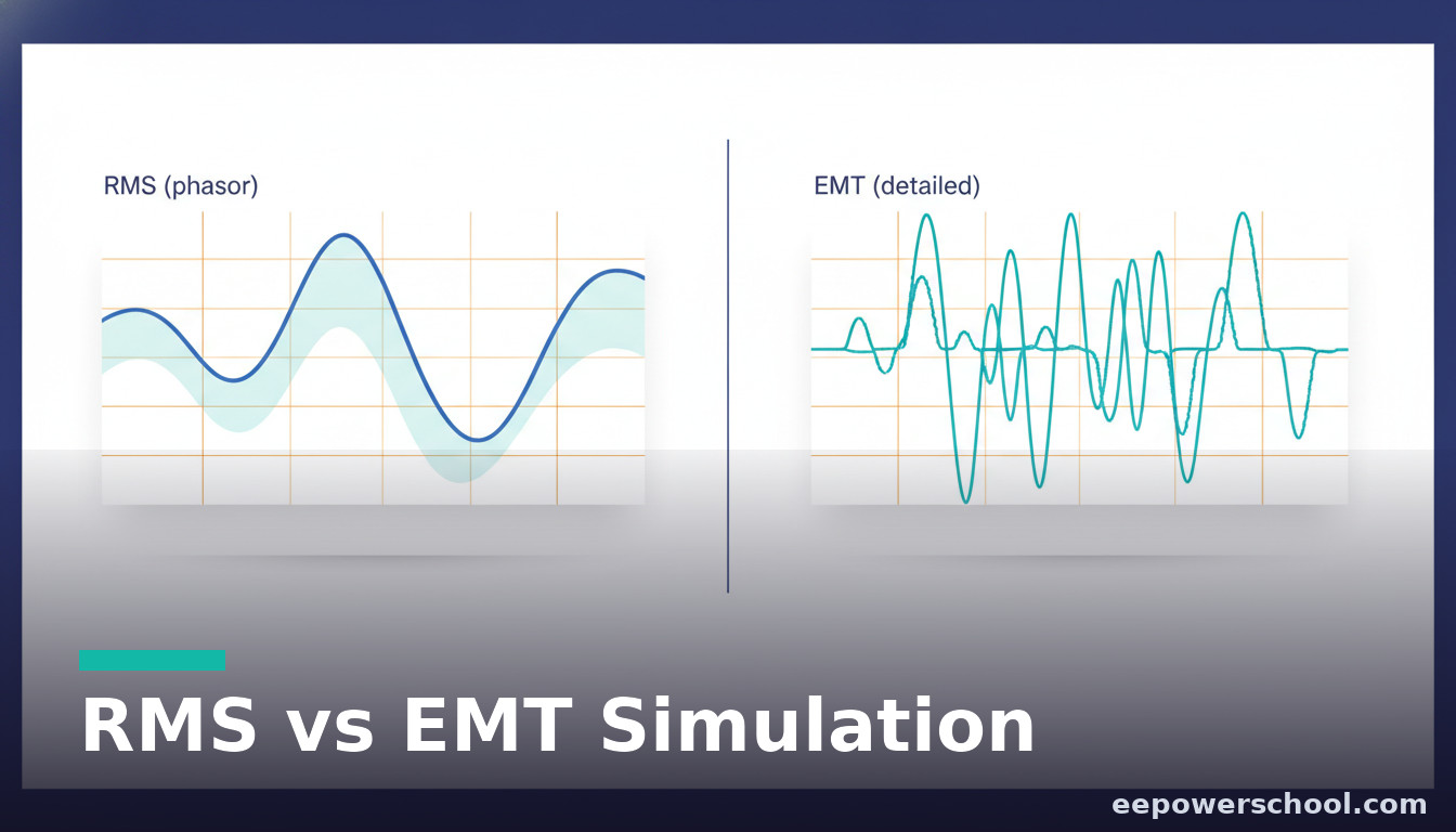
At the root, RMS and EMT differ in what they represent. An RMS (phasor) simulation tracks the magnitude and angle of voltages and currents at the fundamental frequency, assuming the waveform stays a clean balanced sinusoid. An EMT (electromagnetic transient) simulation tracks the actual instantaneous three-phase waveforms, point by point.
That single modelling choice cascades into everything else: the time step, the speed, the phenomena each can capture, and the tools you reach for. Understanding the trade-off is what lets you choose deliberately rather than by habit.
RMS (Phasor) Simulation: Fast and Sweeping
RMS simulation represents each quantity as a phasor that varies slowly compared with the 50 or 60 Hz carrier. Because it ignores the fast waveform detail, it can take large time steps, often several milliseconds, and simulate large interconnected systems over many seconds quickly.
This makes it the workhorse for classic studies: transient (rotor-angle) stability, frequency response, and long-term voltage behaviour across thousands of buses. Tools such as PSS/E, DIgSILENT PowerFactory (RMS mode), and PSLF are built around it. When the assumption of a balanced, fundamental-frequency sinusoid holds, RMS gives you enormous reach for very little cost.
EMT Simulation: Slow but Complete
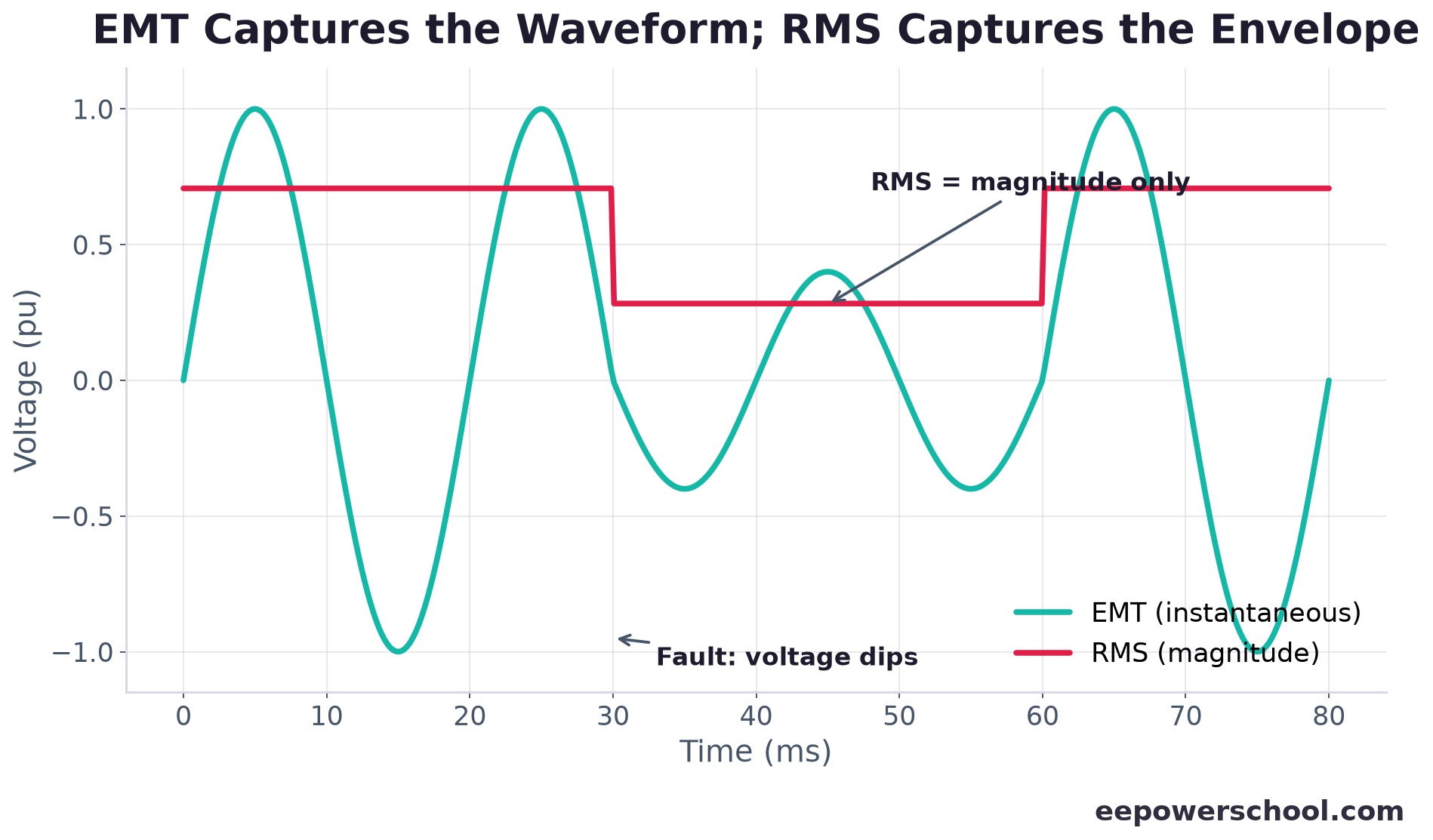
EMT simulation throws away the phasor assumption and solves the instantaneous differential equations of the network, capturing the full three-phase waveform including harmonics, unbalance, switching events, and very fast control action. The price is a tiny time step, typically microseconds, so an EMT case runs far slower and is usually limited to a smaller area of the network.
This is the domain of PSCAD/EMTDC, EMTP, and the EMT modes of modern tools. If a phenomenon lives in the actual waveform, fast power-electronic control, sub-synchronous oscillations, harmonic resonance, EMT is the only way to see it correctly. The chart below contrasts what each method represents for the same event.
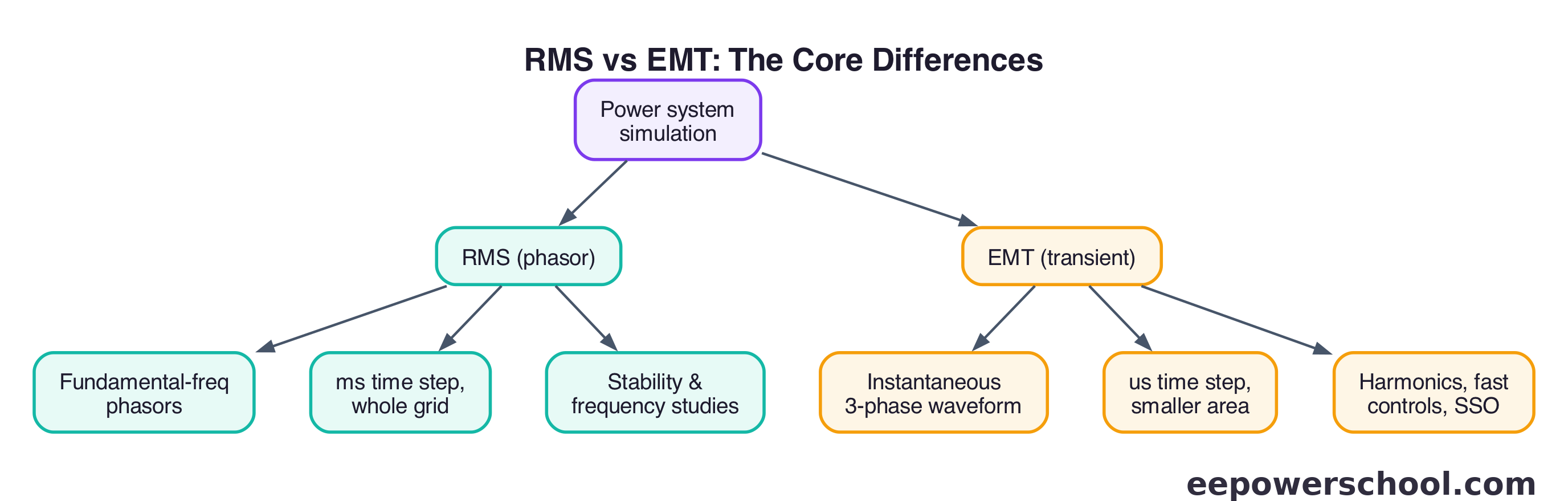
RMS vs EMT: The Core Differences
It is worth laying the trade-offs side by side, because the choice is always a balance of reach against fidelity. RMS buys scale and speed by assuming a clean fundamental-frequency sinusoid; EMT buys fidelity by simulating the real waveform at a tiny time step. The diagram summarises how that one assumption ripples through time step, network size, and the phenomena each tool can represent.
Neither is universally better. The skill is matching the method to the question, and increasingly to the kind of equipment connected at the point of interest.
When RMS Is Enough
When you weigh RMS vs EMT for everyday work, phasor simulation remains entirely adequate for a large share of studies. It is the right tool when the phenomena of interest are slow relative to the fundamental and the system is reasonably strong and balanced:
- Bulk transient and small-signal rotor-angle stability across a wide area.
- Frequency response and inertia studies after generation loss.
- Long-term and large-scale voltage stability assessments.
- Planning studies sweeping many contingencies across thousands of buses.
In these cases the waveform detail EMT provides adds little but costs a great deal, so RMS is not a compromise, it is the correct, efficient choice.
When RMS Is Not Enough
The phasor assumption quietly breaks down exactly where modern grids are heading. RMS becomes unreliable, and EMT becomes necessary, when:
- Inverters connect to a weak grid (low short-circuit ratio), where fast controls interact with the network in ways phasor models cannot represent.
- Converter-driven and sub-synchronous oscillations appear, which the 2021 IEEE/CIGRE classification formally recognised as new stability categories.
- Fast inverter control loops (such as the phase-locked loop) operate on timescales comparable to the fundamental.
- Harmonics, resonance, or significant unbalance matter.
NERC and grid operators have responded by requiring EMT studies for many new inverter-based connections. The pattern is clear: as system strength falls and control speed rises, the validity of RMS shrinks.
Hybrid RMS-EMT Co-Simulation
You rarely need the whole continent in EMT. The practical answer is hybrid co-simulation: model the local area of interest, say a cluster of inverter-based plants on a weak corner, in full EMT, while representing the vast remaining network as an equivalent in RMS.
This keeps the fidelity where it matters and the speed everywhere else. Building and validating the interface between the two domains takes care, but hybrid studies have become a standard way to get EMT-grade answers for a focused problem without paying EMT compute costs for the entire grid.
Choosing the Right Tool: A Practical Guide
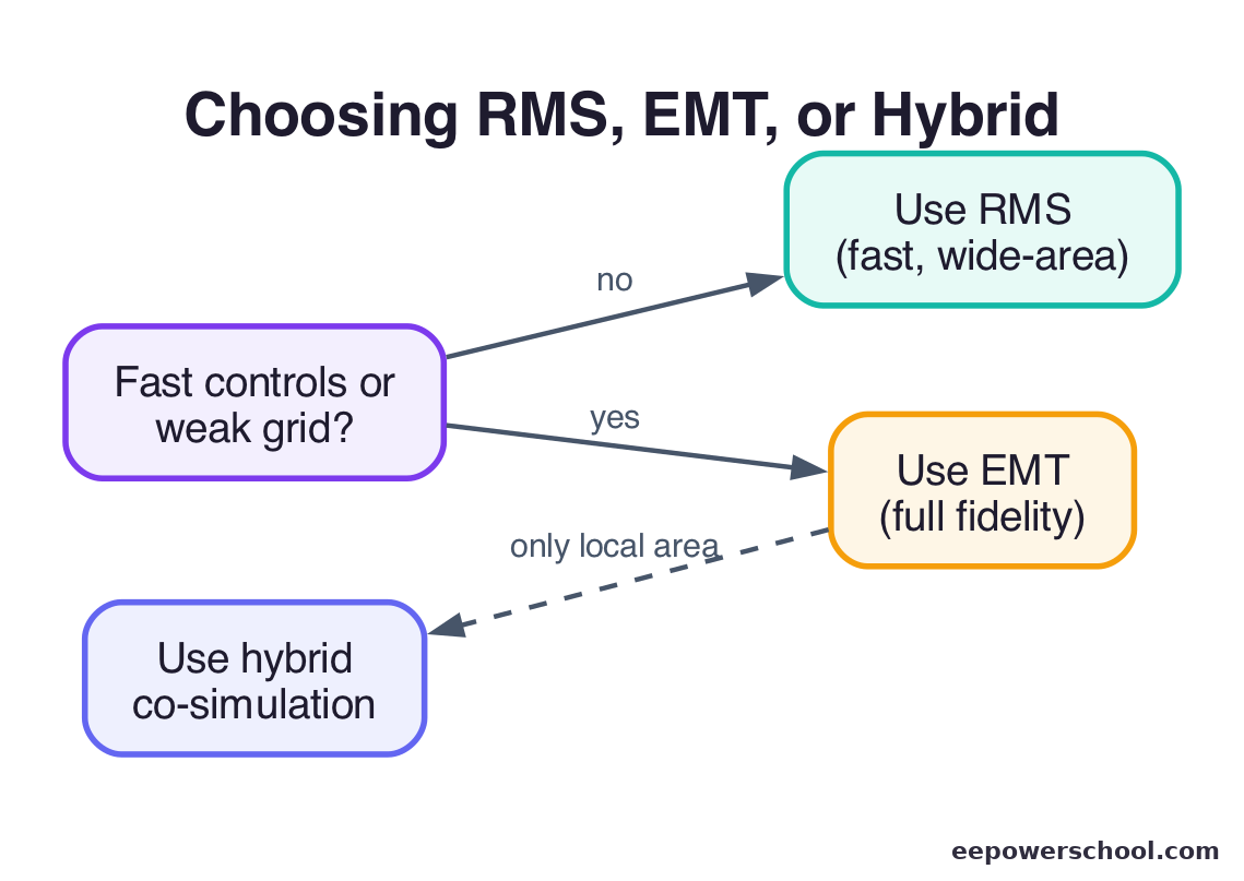
A workable rule of thumb: start in RMS, and switch to EMT when the question touches fast power-electronic behaviour or a weak grid. Concretely, reach for EMT when the connection point has a low short-circuit ratio, when you are investigating oscillations or control interactions, when harmonics or unbalance are central, or when a grid code simply requires it for the connection.
Stay in RMS for wide-area rotor-angle and frequency stability, large contingency sweeps, and long-term voltage studies on a strong network. And when only part of the system needs the detail, reach for a hybrid study. Choosing well between RMS vs EMT is now one of the defining judgement calls in modern power system analysis, and getting it right is the difference between a study that reassures and one that actually catches the problem.
Frequently Asked Questions
What is the difference between RMS and EMT simulation?
RMS (phasor) simulation tracks the magnitude and angle of voltages and currents at the fundamental frequency, assuming a clean sinusoid, and uses large time steps. EMT (electromagnetic transient) simulation solves the actual instantaneous three-phase waveforms at a tiny time step, capturing harmonics, switching, and fast control action.
When do I need EMT instead of RMS?
Use EMT when fast power-electronic behaviour or a weak grid is involved: low short-circuit ratio connections, sub-synchronous or converter-driven oscillations, fast control-loop interactions, or studies where harmonics and unbalance matter. Many grid codes now require EMT for new inverter-based connections.
Why is EMT simulation so much slower than RMS?
EMT solves the network's instantaneous differential equations and must resolve the actual waveform, so it uses microsecond time steps versus the millisecond steps of RMS. That far finer resolution, often a thousand times more steps, makes EMT much slower and usually limited to a smaller area.
What tools are used for RMS and EMT studies?
RMS (phasor) studies commonly use PSS/E, DIgSILENT PowerFactory in RMS mode, and PSLF. EMT studies use PSCAD/EMTDC, EMTP, and the EMT modes of modern tools. Hybrid co-simulation combines an EMT area with an RMS equivalent of the wider network.
What is hybrid RMS-EMT co-simulation?
It models the local area of interest in full EMT while representing the rest of the network as an RMS equivalent. This keeps high fidelity where fast dynamics matter and speed everywhere else, giving EMT-grade answers for a focused problem without EMT compute costs for the whole grid.
Related reading
- Inverter-based resources: the future of renewable energy
- Grid inertia 101: frequency dynamics and the modern grid
- Inverter basics: classification and applications
- Electrical Engineering Formula Cheat Sheet (power systems quick reference)
References
- Hatziargyriou et al. (2021), Definition and Classification of Power System Stability – Revisited & Extended, IEEE Trans. Power Systems
- NERC — 2023 Inverter-Based Resource Performance Issues report
- AEMO — System strength in the NEM explained
- IEEE Std 2800-2022 — interconnection of inverter-based resources